SITL and HITL Simulations using PCC - Aerodynamic Decelerator Systems Laboratory
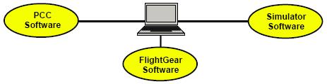
Figure T. Setup for the FlightGear-flight-simulator-based SITL.
a) 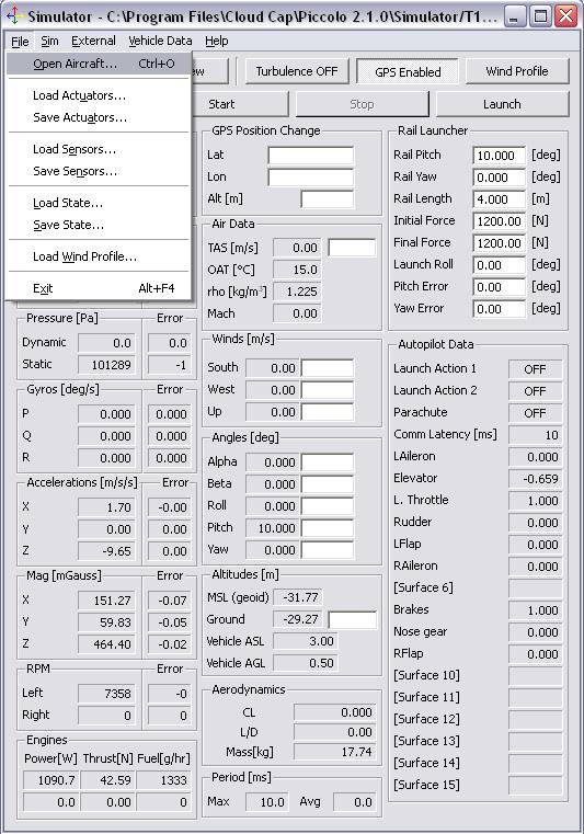
b) 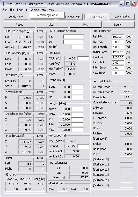
Now, the file that was just saved should be opened in PCC using the Open button in the Vehicle folder of the Controller Configuration option of the Window drop-down menu of the main PCC screen (the very first button in Fig.W).
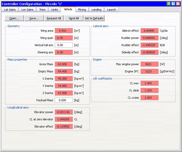
Figure W. Loading the model into Piccolo Command Center.
When loading the model several warnings might pop up informing that some of parameters, say Vertical Tail Arm Payload Mass, are not defined. These undefined parameters need to be defined in the Vehicle screen directly. These data (a local model) need to be uploaded to the Piccolo autopilot. This is done by unlocking the default configuration in the Preflight screen as shown in Fig.X and then clicking on the Send All button on the vehicle screen (Fig.W). Now, both models, local on the ground computer and global on the Piccolo autopilot will have the same model of UAS.
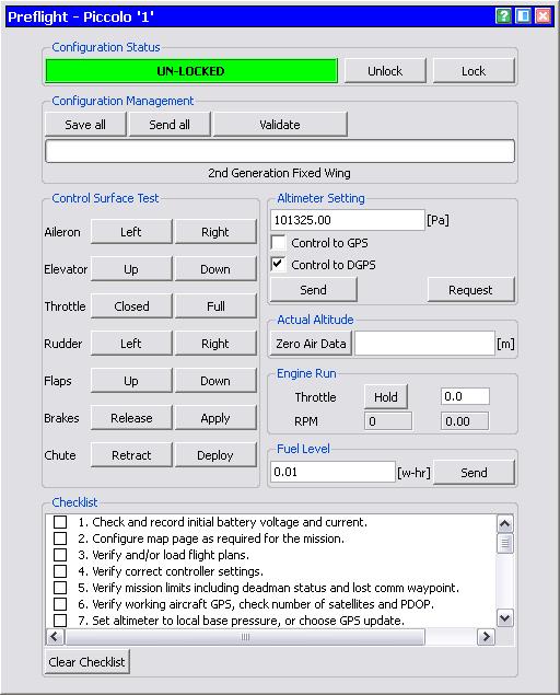
Figure X. Unlocking the current configuration in Piccolo Command Center.
Now that the model is loaded into Piccolo Simulator and PCC (PCC uses a small portion of the complete model used by Piccolo Simulator), everything is ready for simulations.
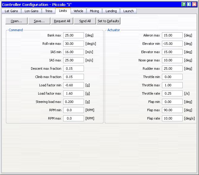
Based on (quite qualitative) results of SITL simulation the user might want to adjust the controller gains (if really necessary) on the two pages of the Controller Configuration windows (see Fig.Y).
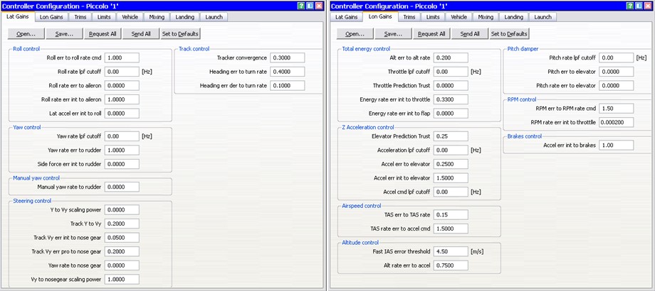
Figure Y. Lateral and longitudinal gains of the Piccolo controller.
a) 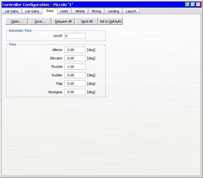
b)