Simulink Modeling - Aerodynamic Decelerator Systems Laboratory
ADSC - RPT - Aircraft Aerodynamics - Fig P
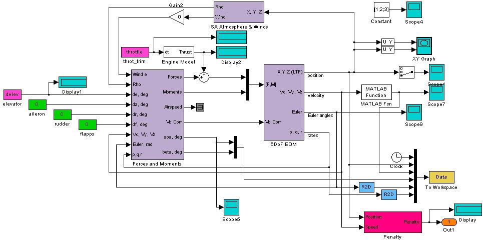
Figure P. Top view layer of the developed Simulink model.
ADSC - RPT - Aircraft Aerodynamics - Fig Q
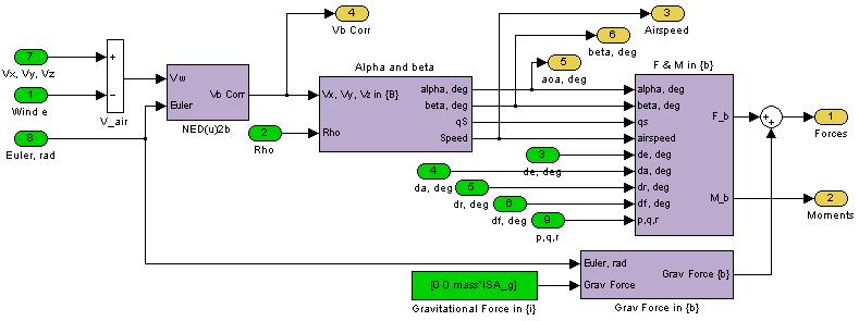
Figure Q. Computation of forces and moments.
ADSC - RPT - Aircraft Aerodynamics - Fig R
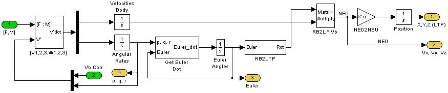
Figure R. Modeling 6DoF equations of motion.
Nested Applications
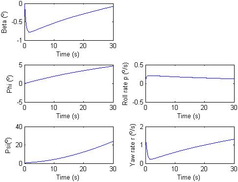
Figure Sa
a) 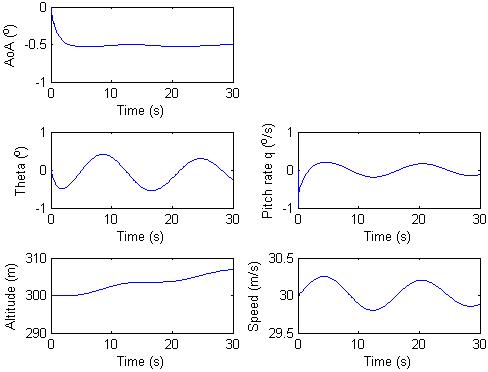
Fig Sc
c) 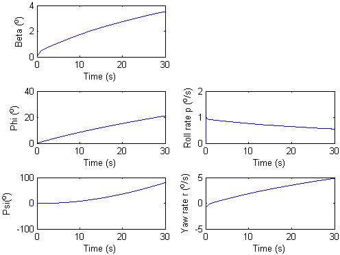
Figure Sb
b) 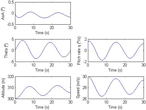
Fig Sd
d)