
Development of a Detect and Sense Capability - Aerodynamic Decelerator Systems Laboratory
Development of a Detect and Sense Capability
As well known, “Detect, Sense and Avoid” or “See and Avoid” capability is the key capability that precludes unmanned aerial systems (UAS) from operating in the national airspace. Once a potential threat is detected, its dynamics needs to be assessed to proceed with the following steps, collision maneuver computation and execution.
This research effort deals with the development of computer algorithms to automatically analyze video streams provided by onboard electro-optical (EO) and infrared (IR) sensors. The essence of developed algorithms is to use image-processing methods to segment the shape of the object in each video frame. As shown in example in Fig.A, pixel operations are conducted to determine the location of gradients that correspond to edges of objects. These edges are then dilated to form connecting lines, and the connecting lines that enclose areas are filled to form bodies. When a large body is found, it is compared to an active shape model to classify the body as the desired object. With subpixel accuracy, the developed code is able to identify key points on the object for further assessment of object’s position and orientation in the camera frame. If using multiple cameras (stereovision) or a single camera (superimposing multiple images taken at different points along a trajectory at successive time instances), so that the location, azimuth and elevation of each shot is known, it is also possible to automatically perform the so-called pose estimation (determine time-space-position information) of the object throughout the video.
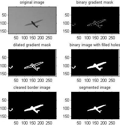
Figure A. Segmentation of UAS from a video frame.
Figure B illustrates application of developed algorithms for a different problem when a field view of a high-speed camera captures two aerial objects on a collision course. The goal in this case is to use images provided by multiple cameras to estimate relative kinematics of these two objects and distance between them.

Figure B. Evaluation of intercept geometry.
Figures C-F demonstrate the results of a feasibility study on assessing capability of UAS to detect the launch of ballistic missile. Specifically, Figs.C shows two snapshots taken from two different aerial locations with respect to the launch site, while Fig.D presents the result of applying the developed code to detect the launch event. Figure E demonstrates a similar capability to detect a missile launch using a ground or low-altitude camera. Figure F illustrates how the developed code works, providing inputs to the guidance block of the attack aircraft to intercept a ballistic missile at the boost phase.
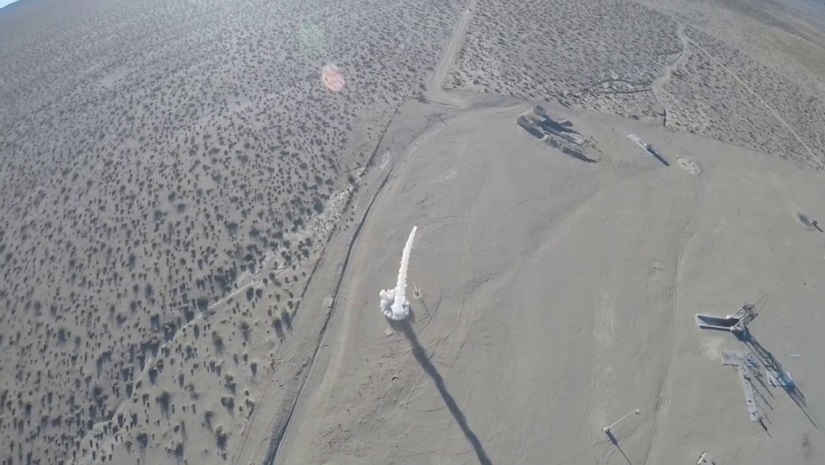
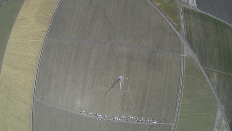
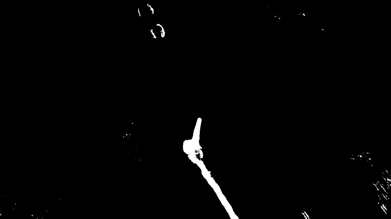
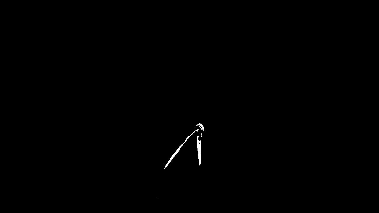
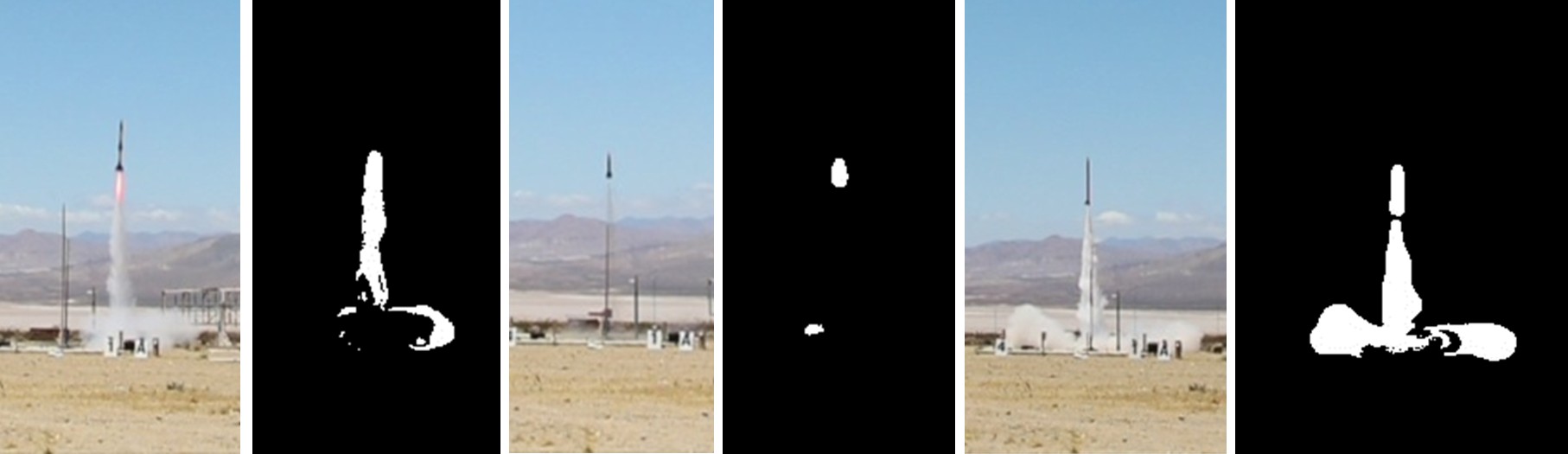
Figure E. Missile launches and the corresponding background subtraction frames.
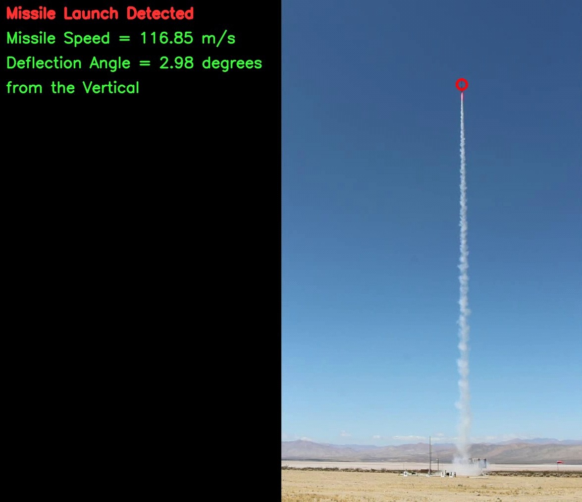
Figure F. Rocket tracking and estimation of speed and trajectory declination angle.